This chapter describes how value stream objects can be used and interconnected.
Contents
5. Plausibility check visualization
To add an object from the Toolbox to the modeling area, simply drag & drop the desired object from the Toolbox to any position in the modeling area (see Figure 1).
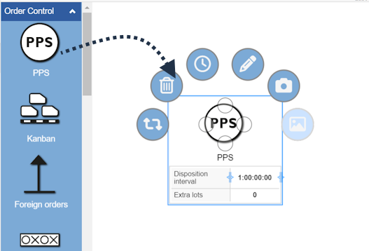
Figure 1 - Adding objects to the modeling space
|
Note: Since version 3.16 an algorithm helps the user modeling and suggests possible objects to connect to the currently selected. The suggested items are based on probabilities calculated by the algorithm. Please note that not all possible objects are displayed |
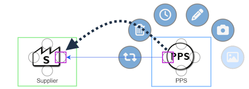
By clicking on the connection points of the object, possible object suggestions are displayed as calculated by the algorithm.
The number of suggestions can be set in the App settings (global) section 2.9 Number of suggested items
Probabilities are displayed for each suggested object. By clicking on the respective object it is automatically connected to the original object in the modeling surface.

Figure 2 - Suggested objects
The position of the suggestions displayed for a new object depends on which connection point is selected in the original object.
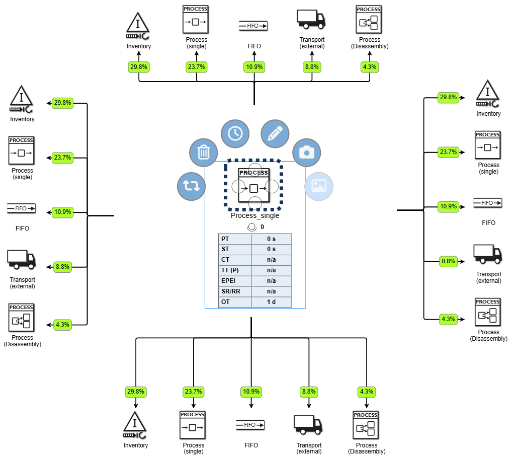
Figure 3 - Position of suggestions
To copy an existing object, the desired object must first be selected with the mouse. The selected object can then be copied and pasted using one of the following options:
•Using the key combination [CTRL] + C and [CTRL] + V
•By clicking on the desired object, then holding down the [CTRL] key and dragging the object to another location
•Copying and pasting objects is also possible between several alternatives of the same project
To select an object, simply click on the desired object with the mouse. You can also select several objects by holding down the [CTRL] key.
By holding down the mouse button for longer ("long click") a frame can be drawn up to mark several objects (see Figure 2).
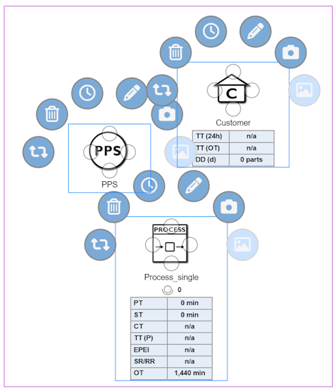
Figure 2 - Frame to mark multiple objects
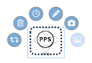
Objects can be connected to each other via connecting lines. Each object from the Toolbox has four possible connection points, marked by a circle (see Figure 3).
A connection to another object can be established by clicking and holding down the left mouse button. The connection automatically docks to one of the four possible connection points of the target object.
The possible connections for an object are indicated by a green frame in the modeling area (see Figure 4).
Figure 3 - Connections points of an object |
Figure 4 - Possible connections |
The connections are also divided into the categories material flow, information flow, Kanban and rework.
If only one link type is allowed between two object types, this one will be automatically selected. If several types are allowed, you can then select a corresponding type.
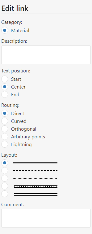
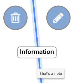
By clicking on the connections, a ring menu appears which can be used to either delete or edit the connection.
In addition to a description, the information on the category, text alignment, routing and layout of the link can be edited in the side menu.
In addition, a text can be stored in the comment field, which appears in the modeling interface as a tool tip (see Figure 6).
Figure 5 - Editing the connection |
Figure 6 - Edit connection |
5. Plausibility check visualization
These errors are indicated by the yellow exclamation mark icon |
|
in the modeling interface. |
Additionally, a Tooltip appears when you hover the mouse over the icon. A dialog providing information about the error is displayed when you click the icon.
If it is not possible to find all predecessors/successors with a product connection for an object with a product definition (at least one predecessor/at least one successor depending on the check direction), an error is displayed.
Checking for these validations can be enabled or disabled in the local project options.
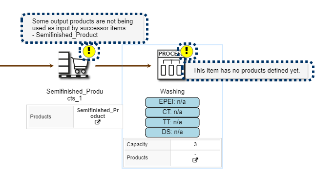
Figure 7 - Error in Product Transitions
As soon as an invalid control is modeled, a warning is displayed to the user. In the following example, an information flow link from the PPS system to the depicted warehouse is missing.
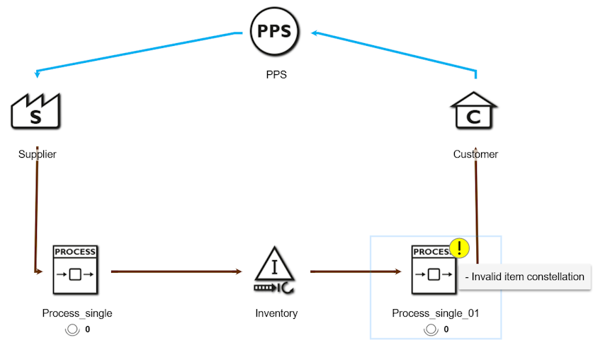
Figure 8 - Error in Control constellations
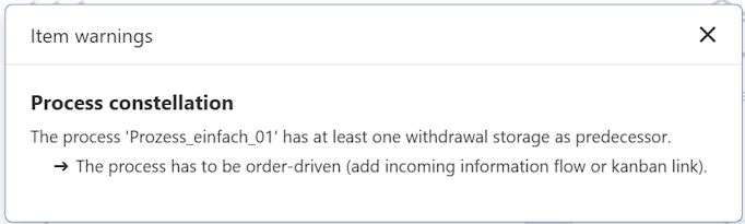
Figure 9 - Error in Control constellations dialog
A list of all possible predecessors and successors of the individual value stream objects can be found in the chapter Objects of the value stream toolbox in the respective section.
© SimPlan AG - Hanau District Court, Commercial Register (Part B) 6845 - info@simplan.de - www.simplan.de/en