In this chapter, the use of products and parts lists is presented. Products can be created in different ways:
Either in the local project settings in the Products tab, or directly via, for example, the Select product option when creating a parts list of an object.
All created products and parts lists are graphically displayed here in an automatically created view (see Figure 1).
Various elements can be added from the toolbar on the left: in addition to Text items, Drawing elements (Rectangle, Ellipse, Triangle) and a Background Image are now available.
Product nodes can also be enriched with images to visually represent products.
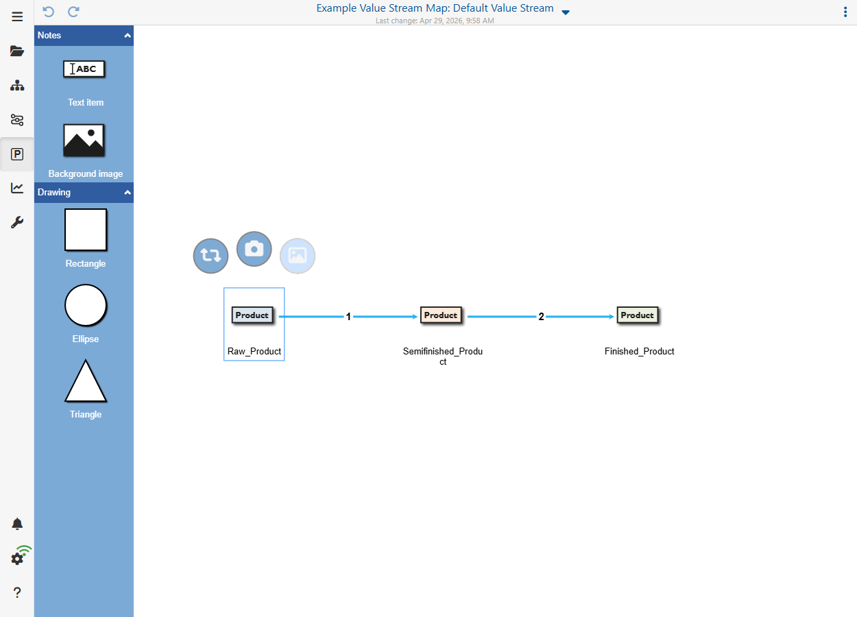
Figure 1 - Products and Parts Lists Overview
Clicking on the menu button with the three dots in the upper right corner of the application opens a drop-down menu. The individual entries are explained below.
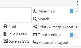
Figure 2 - Menu
Mini-map
With this Mini Map switch an overview window can be shown and hidden, which helps to keep the overview especially with larger product lists.
Search
By clicking on Search, objects can be searched for via a dialog. The figure below shows the dialog with the drop down menu open, which contains all objects used on the modeling surface.
![]()
Figure 2 - Search for objects
As soon as an element has been selected and the search has been started via the Search button, the corresponding element is then selected on the modeling surface and this is centered on the respective object.
Print & Image Export
Clicking on Print & Image Export opens a dialog that can be used to print or save the content as PNG or SVG.

Figure 5 - Print and export
Tabular editor
Clicking the switch Tabular editor opens a tabular view on the right side of the window, in which all products are listed again.
![]()
Figure 4 - Tabular View of Products
Automatic Layout
Clicking on Automatic Layout opens a dialog that can be used to automatically align the content.
![]()
Figure 3 - Auto Layout Dialog
If you click on a product, and then on the Icon Editor symbol |
|
the icon editor from Figure 6 opens, in which the appearance of the object can be adapted. |
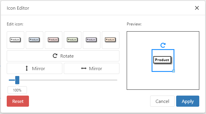
Figure 6 - Product Icon Editor
The number between the connecting lines of the respective products indicates how many products of the left product are needed to create the right product.
In this example, one Raw_Product is needed to create the Semifinished_Product product and two Semifinished_Products are needed to create the Finished_Product product.
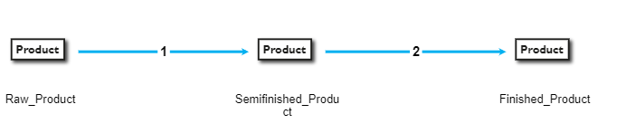
Figure 7 - Product List in Detail
Clicking on the connection line opens a side menu on the right side.
Here the link line can be formatted. Details can be found in chapter Handling value stream objects in section 4. Connecting objects.
© SimPlan AG - Hanau District Court, Commercial Register (Part B) 6845 - info@simplan.de - www.simplan.de/en