Contents
Step 8 - Confirmation of alternative
Step 9 - Start simulation of alternative
Step 10 - Results of alternative
Step 11 - Comparison of Results
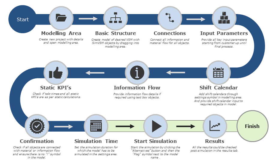
Figure 1 - Overview of model creation
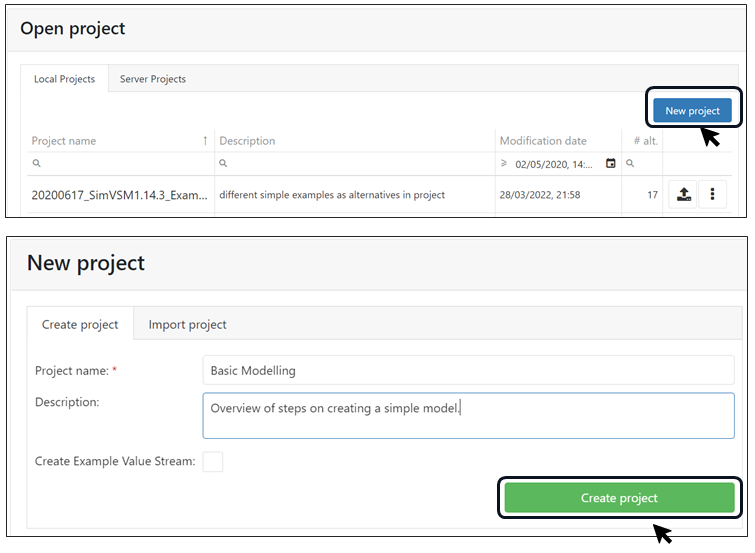
•Create new project with details and open modeling area.
|
Figure 2 - Modeling area |

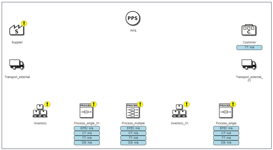
•Create model of desired VSM with SimVSM objects by dragging into modeling area.
•Drag the required input objects into the modeling area.
•Form a basic structure similar to a static VSM model.
|
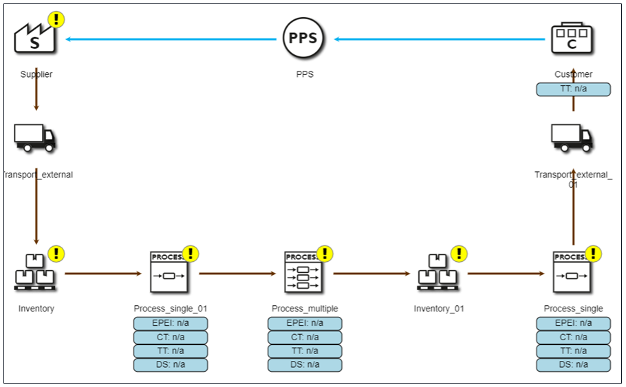
Figure 3 - Basic structure |
•Connect all information and material flow for all objects.
•After placing the objects, provide all the basic connection requirements for material flow.
|
Figure 4 - Connections |

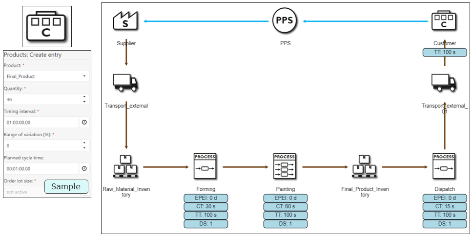
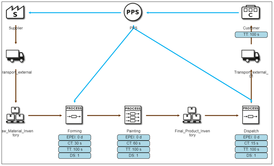
•Provide all key input parameters starting from customer up until final process.
•Name all the process objects and provide all necessary inputs for the simulation.
|
Figure 5 - Input parameters |
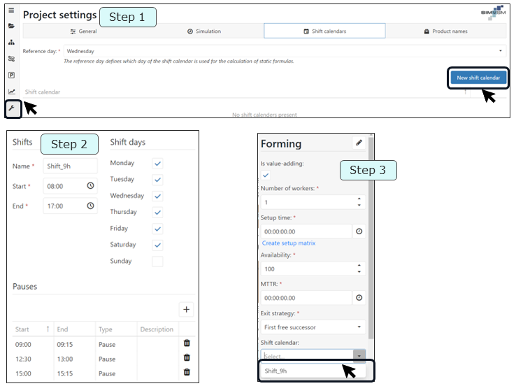
•Add shift calendars through settings symbol in modeling area. And provide shift calendar input to required objects in model.
•Step 1: Create a new shift calendar.
•Step 2: Input the shift time and pauses if any. Select the days in which the shift is applicable.
•Step 3: After creating shift calendar, add the shift calendar to objects wherever it is required.
|
Figure 6 - Shift calendar |

•Provide information flow details if required using text box objects.
•Connect the key information flow in the model.
•Add labels if required by using the notes object in the modeling area.
|
Figure 7 - Information flow |

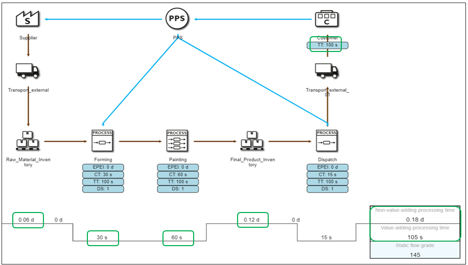
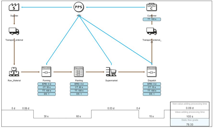
•Check if tact times and all static KPIs are as per static calculations.
•Check for the key static KPIs to check if input parameters meet the expectations.
|
Figure 8 - Static KPIs |

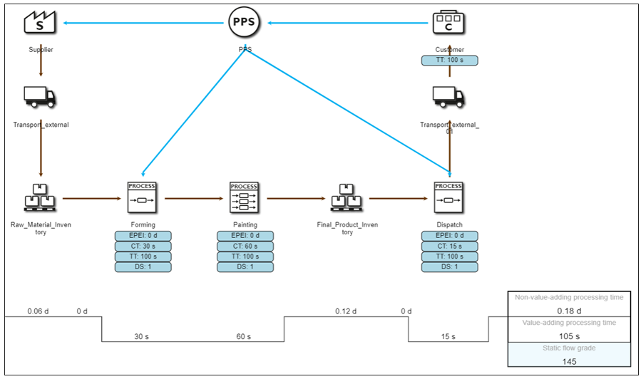
•Check if all objects are connected with material or information flow.
•Ensure there is no "!" symbol in the model.
|
Figure 9 - Confirmation |

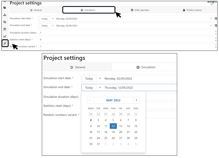
•Set the simulation duration for which the model has to be simulated in the settings area.
|
Figure 10 - Simulation time |
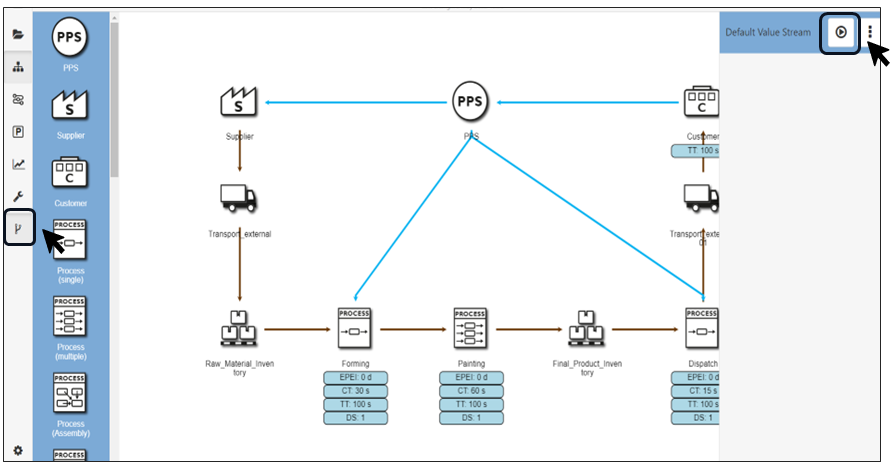
•Start the simulation by clicking the Alternatives button.
•After providing the simulation duration the simulation could be initiated.
•The Status button will initiate simulation and progress can be seen on the display
|
Figure 11 - Start simulation |

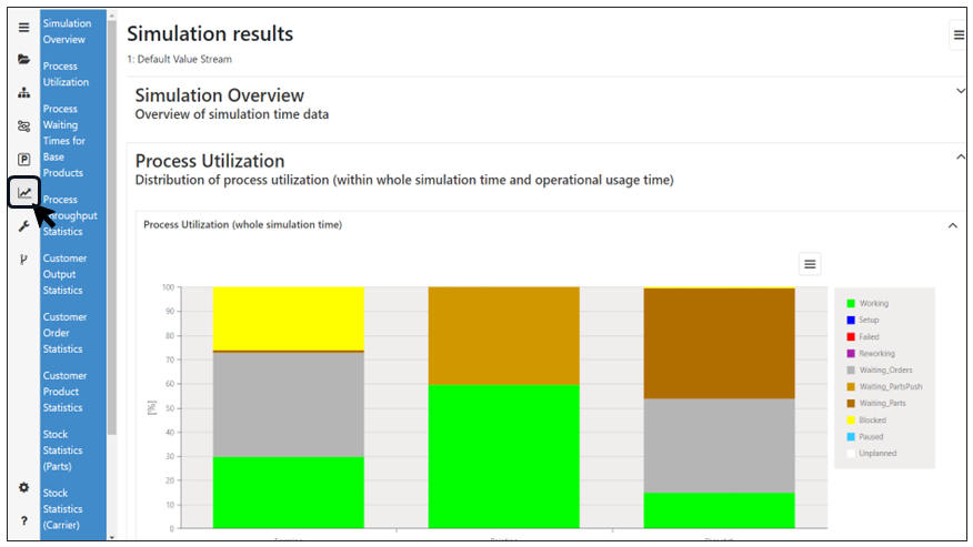
•All the results could be checked post simulation in the results tab.
•Post simulation results could be viewed in the results tab.
•Multiple sections are available for interpretation and improvement.
|
Figure 12 - Results |

Step 8 - Confirmation of alternative
•Check if all objects are connected with material or information flow.
•Ensure there is no "!" symbol in the model.
|
Figure 13 - Confirmation of alternative |
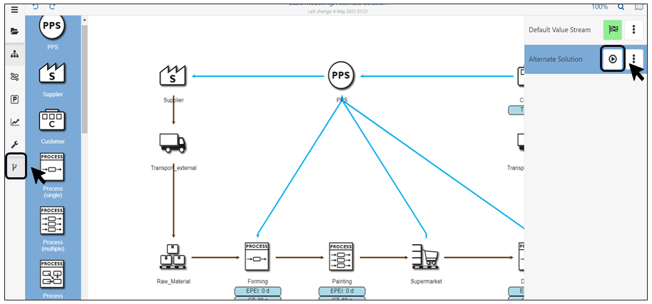
Step 9 - Start simulation of alternative
•Start the simulation by clicking the Alternatives button.
•After providing the simulation duration the simulation could be initiated.
•The Status button will initiate simulation and progress can be seen on the display
|
Figure 14 - Start simulation of alternative |
Step 10 - Results of the alternative
•All the results could be checked post simulation in the results tab.
•Post simulation results could be viewed in the results tab.
•Multiple sections are available for interpretation and improvement.
|
Figure 15 - Results of the alternative |

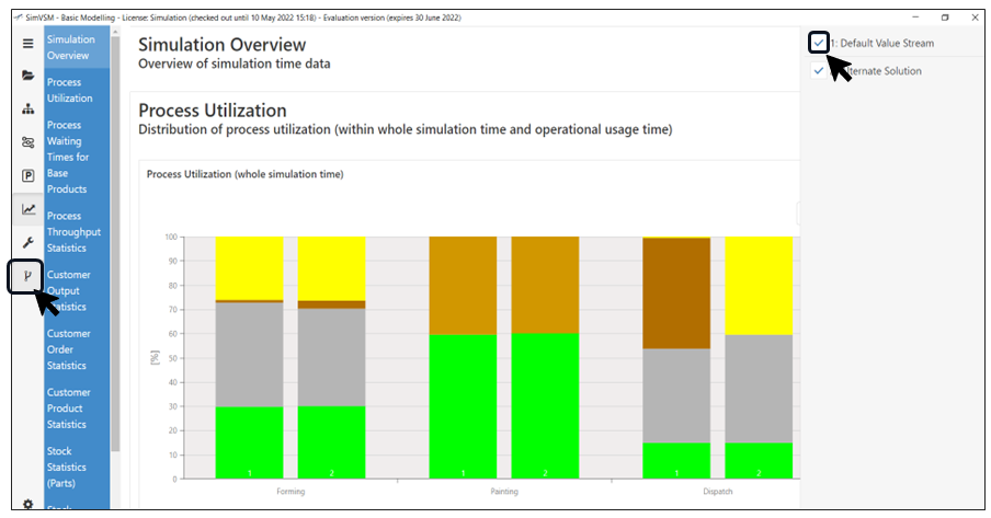
Step 11 - Comparison of Results
•The results of alternatives could be directly compared with basic model to visualize the improvements.
•By using alternate button, 2 different model could be selected for comparison of results
|
Figure 16 - Comparison of results |

© SimPlan AG - Hanau District Court, Commercial Register (Part B) 6845 - info@simplan.de - www.simplan.de/en